How to install fifth wheel coupling correctly
Installing a semi trailer fifth wheel is not simply a matter of bolting a coupling plate to the tractor frame. The installation must produce the correct coupling height, kingpin engagement, mounting torque, load distribution, and release-system clearance. This how to install Fifth Wheel Coupling guide explains the complete process for mechanics, fleet owners, and trailer operators who need a reliable tractor trailer connection without premature wear, coupling failure, or inspection rejection.
Common problems include a fifth wheel that sits too high, uneven mounting brackets, loose fasteners, a handle that will not return, excessive kingpin play, or a trailer that cannot be uncoupled safely. The solution is a controlled installation followed by measured inspection. Linfeng recommends treating the fifth wheel, mounting brackets, kingpin, locking jaws, and trailer landing gear as one connected system rather than as separate parts.
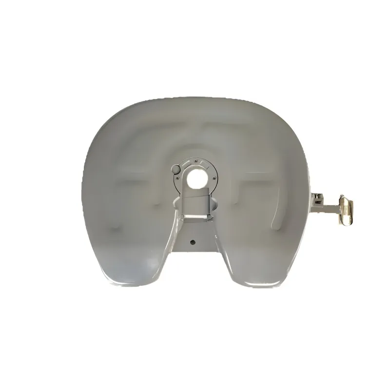
A fifth wheel transfers vertical trailer load and longitudinal braking and acceleration forces through a relatively small contact area around the kingpin. A mounting error of only a few millimeters can alter trailer clearance, axle loading, or the angle of the trailer suspension.
Incorrect coupling height: may cause the trailer to ride nose-high or nose-low, increasing tire wear and reducing braking stability.
Insufficient mounting torque: allows bracket movement and fretting around bolt holes.
Over-torqued fasteners: may stretch bolts or damage the mounting structure.
Incomplete kingpin engagement: can produce a false coupling that may separate under load.
Poor release-cable routing: can prevent the locking mechanism from closing or releasing correctly.
Incorrect load rating: creates a structural mismatch between the tractor, fifth wheel, and trailer.
Before work begins, compare the fifth wheel’s rated vertical load and drawbar rating with the tractor and trailer data plate. In North America, inspection requirements commonly reference Federal Motor Carrier Safety Regulations such as 49 CFR 393.70 and periodic inspection requirements under 49 CFR 396.17. European and other markets may use different requirements, so the manufacturer’s installation manual and local regulations remain controlling.
Why Correct Fifth Wheel Coupling Installation Matters
Required Preparation for a Fifth Wheel Coupling Installation
Record the following information before removing the old unit:
| Item | What to verify | Why it matters |
|---|---|---|
| Rated vertical load | Matches or exceeds the maximum imposed trailer load | Prevents overload of the coupling plate and mounting structure |
| Kingpin size | 2-inch or 3.5-inch design, depending on the coupling | Prevents incompatibility between kingpin and locking jaws |
| Mounting pattern | Hole spacing, bracket width, bolt diameter, and frame interface | Ensures the brackets sit squarely on the tractor chassis |
| Coupling height | Manufacturer’s unloaded and loaded height range | Controls trailer attitude and clearance |
| Release mechanism | Left-side, right-side, cable, air, or manual design | Determines routing and adjustment requirements |
| D-value or drawbar rating | Must meet the vehicle combination calculation | Controls longitudinal towing capacity |
Do not select a replacement based only on the physical width of the fifth wheel. A coupling plate that fits the chassis may still have the wrong load rating, kingpin geometry, bracket height, or locking-jaw design.
Confirm the Fifth Wheel Coupling Specification
Certified lifting equipment or a workshop crane rated above the fifth wheel assembly weight
Wheel chocks and parking-brake verification equipment
Socket set, breaker bar, impact wrench for removal only, and calibrated torque wrench for final tightening
Steel rule, tape measure, straightedge, digital angle gauge, and vernier caliper
Wire brush, approved degreaser, lint-free cloths, and inspection light
New manufacturer-approved mounting bolts, nuts, washers, and locking devices
Thread lubricant or anti-seize only where the installation manual permits it
Grease meeting the fifth wheel manufacturer’s specification
Personal protective equipment: safety footwear, gloves, eye protection, and hearing protection
Torque chart and installation manual for the exact fifth wheel model
Never reuse critical mounting bolts unless the manufacturer specifically allows reuse. A torque value applies to a particular bolt grade, coating, thread condition, and lubrication state. For example, a dry M20 bolt and a lubricated M20 bolt can produce substantially different clamping forces at the same wrench torque.
Tools and Materials for Fifth Wheel Coupling Installation
Park the tractor on a firm, level surface.
Apply the parking brake and place transmission controls in the manufacturer-recommended safe position.
Chock the wheels on both sides of the tractor.
Disconnect electrical, air, and auxiliary lines before lifting or removing the old coupling.
Support the fifth wheel independently. Never rely on an impact wrench, hydraulic jack, or single lifting point as the only support.
Keep personnel outside the crush zone between the fifth wheel plate, tractor frame, and trailer.
Confirm that the replacement assembly is not cracked, distorted, contaminated, or missing locking components.
Safety Prerequisites Before Installing a Semi Trailer Fifth Wheel
How to Install Fifth Wheel Coupling Step by Step
Before disassembly, measure and record the existing setup. Measure from the ground to the top of the coupling plate at both left and right sides, then measure from the rear axle centerline to the center of the kingpin contact area. Also record the distance between the fifth wheel and the cab, fuel tank, rear axle, and suspension components.
A practical inspection tolerance is to investigate any left-to-right height difference greater than approximately 3 mm, although the exact allowable value depends on the chassis and coupling manufacturer. Measure the tractor frame diagonals if the mounting rails appear twisted. A diagonal difference of several millimeters can indicate a frame or bracket alignment problem rather than a fifth wheel problem.
Step 1: Measure the Existing Fifth Wheel Installation
Remove dirt, grease, and loose paint from the mounting surfaces. Inspect the frame rails for:
Elongated or oval bolt holes
Cracks near crossmembers and bracket corners
Corrosion deeper than surface discoloration
Previous unauthorized drilling or welding
Twisted, bent, or uneven mounting brackets
Interference with air lines, wiring, suspension components, or exhaust parts
Use a straightedge across each bracket. The coupling should sit on clean, stable contact surfaces without rocking. Do not correct a distorted bracket by forcing it into position with the bolts. Replace or repair the structure according to the chassis manufacturer’s approved procedure.
Step 2: Inspect the Tractor Frame and Mounting Brackets
Lift the fifth wheel into position and align the mounting holes without inserting bolts fully. The plate should be centered laterally on the chassis unless the vehicle manufacturer specifies an offset installation.
Check three clearances before tightening:
At least the manufacturer’s specified clearance from the cab during maximum articulation.
Clearance from the rear axle and suspension during full suspension movement.
Clearance for the release handle, air cylinder, sensor, and lubrication points.
Do not assume that a static clearance is sufficient. A tractor-trailer combination articulates during turning, reversing, uneven-road travel, and trailer loading. A clearance that looks acceptable when parked may disappear when the suspension compresses.
Step 3: Position the Fifth Wheel Coupling
Inspect the mounting surface, coupling plate, locking jaws, and kingpin engagement before road testing.
Step 4: Install Approved Mounting Hardware
Install new bolts, washers, nuts, and locking devices in the exact order shown in the product manual. Finger-tighten all fasteners first. This allows the assembly to settle naturally and prevents one bolt from pulling the bracket out of alignment.
Do not substitute ordinary hardware for high-strength structural fasteners. Confirm the bolt grade, diameter, thread pitch, coating, and length. At least two full threads should normally extend beyond the nut after final tightening, unless the manufacturer specifies a different arrangement.
Step 5: Align the Coupling and Tighten the Bolts
Tighten the fasteners in a cross-pattern or the sequence specified by the manufacturer. Use a calibrated torque wrench for the final pass. A useful workshop control is to apply torque in two stages, such as approximately 50% followed by 100% of the specified value, but the manufacturer’s sequence takes priority.
Do not publish or apply one universal torque value to every fifth wheel. Values vary with bolt size, grade, coating, lubrication, bracket design, and coupling model. Record the actual final torque, wrench identification, calibration date, technician, and installation date on the service sheet.
For quality control, a torque wrench used for structural installation should be calibrated at the interval required by the workshop quality system; many fleets use a 12-month interval, with additional verification after impact or overload. A torque audit should be performed on a sample of completed installations rather than relying only on the technician’s memory.
Step 6: Connect and Adjust the Release Mechanism
Route the release cable or air line away from sharp edges, exhaust heat, moving suspension parts, and pinch points. The cable should have a smooth bend radius and should not be pulled tight when the fifth wheel is in its normal operating position.
Operate the handle several times. It should move through its full travel without binding and should return to the locked position when the mechanism is reset. If the release indicator does not correspond with the jaw position, stop the installation and inspect the linkage. A visible handle position alone is not proof that the kingpin is locked.
Step 7: Lubricate the Fifth Wheel Plate and Locking Mechanism
Clean the coupling plate before applying grease. Apply an even film to the kingpin contact area, throat, and manufacturer-approved locking surfaces. Excess grease can collect abrasive dust, while insufficient grease increases metal-to-metal wear.
Use the grease grade specified for the coupling. Some low-maintenance or polymer-lined designs require different lubrication practices, and applying conventional grease to an incompatible liner may damage the material or invalidate the warranty.
Step 8: Inspect the Trailer Kingpin and Upper Coupler
Measure the kingpin with a vernier caliper at the locations specified by the kingpin manufacturer. Inspect for:
Neck wear or a reduced diameter
Flanging, cracks, gouges, or deformation
Loose or cracked upper coupler mounting bolts
Separation between the upper coupler plate and trailer floor
Uneven wear caused by incorrect fifth wheel height
Do not connect a new fifth wheel to a kingpin with excessive wear. The locking jaws and kingpin must be compatible as a matched coupling system. If the kingpin diameter, wear limit, or profile is outside the manufacturer’s specification, replace or repair it before coupling.
Step 9: Couple the Tractor to the Trailer
Confirm that the trailer brakes are applied and the landing gear is stable.
Open the locking jaws according to the fifth wheel manual.
Align the tractor centerline with the trailer kingpin.
Reverse slowly until the kingpin enters the throat and the jaws close.
Apply the tractor parking brake.
Visually inspect the locking jaws around the kingpin.
Connect air lines and electrical cables.
Raise the landing gear only after the coupling has passed the inspection.
The coupling must not rely on the trailer landing gear to force the kingpin into the lock. If the tractor stops too far forward or the kingpin contacts the front of the throat, uncouple and realign rather than using excessive pulling force.
Step 10: Perform a Pull Test and Visual Lock Test
With the trailer brakes applied and the landing gear still supporting the trailer, apply a controlled low-speed pull against the locked coupling. The purpose is to confirm engagement, not to drag the trailer or overload the landing gear.
After the pull test, perform a second visual inspection. Confirm that:
The locking jaws fully surround the kingpin.
The release handle is in the locked position.
The safety indicator shows locked status, if equipped.
No gap exists between the fifth wheel plate and the trailer upper coupler.
The trailer is not resting on the tractor frame or suspension.
The air pressure remains stable after the lines are connected.
Step 11: Check Coupling Height and Trailer Attitude
Measure the trailer floor or chassis rail relative to the ground on level pavement. The trailer should not be visibly nose-high or nose-low beyond the vehicle manufacturer’s operating range.
A practical field check is to compare the loaded trailer attitude with the manufacturer’s specified kingpin and axle geometry. Excessive nose-high operation can increase aerodynamic drag, alter axle loading, and accelerate wear on suspension components. Excessive nose-low operation can reduce front clearance and increase the chance of contact between the trailer and tractor during articulation.
Step 12: Complete a Road Test and Post-Installation Inspection
Perform a controlled road test in an open area. Begin with low-speed straight-line movement, then test braking, turning, and reverse articulation where safe. Listen for metallic impact, repeated clicking, abnormal suspension movement, or air leakage.
After the first loaded trip, reinspect the mounting bolts, brackets, release mechanism, coupling plate, and kingpin. A practical fleet procedure is to perform this check after the first approximately 50 to 100 km and again during the next scheduled inspection. If the manufacturer specifies a different interval, follow that requirement.


评论
发表评论